[an error occurred while processing this directive] |
[an error occurred while processing this directive] |
The CAD Tools
The Line tool has been provided to make it easier to
position an object which has no 3dfaces at that place which should be
positioned at the origin (0,0,0). An
arch, for example, can be difficult to position because it has no components at
that point which would constitute its bottom, center, rear. But by adding a Line from one side of the
arch to the other at the rear of the model, the model now has a component – the
center point of the guide line – which can be used to snap the model to the
origin point. The series of four images
below illustrates this functionality:
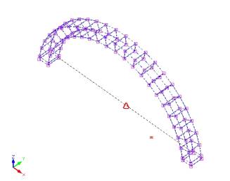
Model
of Arch
Positioning
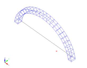
Line User Locks onto
Added Snap Point
At Center of
Positioning Line
Origin Icon
1.
Before Move Operation 2. Object Selected for Move
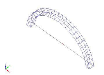
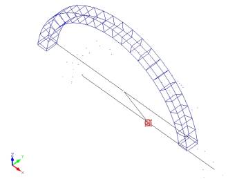
Model Snapped to
User drags Origin
Center of Positioning
Line and Snaps to
Origin Icon
3. Moving Object 4. Move Operation Completed
Objects
often display more clearly if only those edges which comprise the object’s
outline are visible. When you import a 3D
model you may find that you would like to turn off the display of some edges
which appear on the screen or you may find that certain edges don’t display
even though you would prefer that they do.
This tool allows you to choose which 3dfaces’ edges display and which
don’t. The changes you make here will
remain in effect once the model is imported into Chief or any other CAD program
capable of opening or importing .dxf or .dwg files.
To use
this tool:
Invoke
the command by typing either eon (to turn on
3dface edges) or eof (to turn off 3dface edges)
at the Command Line, or by selecting the appropriate command from the CAD menu.
The
prompt “Select Entities” will now be displayed in the Prompt Box. .
You can select all the 3dfaces displayed in the Drawing Window by typing
all in the command line and pressing Enter or by
dragging a selection window around all the objects In the Drawing Window. If you want to select fewer than all the
elements of the objects displayed on screen, you may select them by dragging a
selection window which surrounds or intercepts those items.
After
making your selection press Enter to complete the operation, changing the
visibility of the edges you selected.
When
Object Snap is activated, the selection cursor will lock onto the endpoints and
midpoints of entities on the screen.
This can be helpful when specifying base points and axis points if you
don’t know their exact coordinates for entering into the Command Line and is
crucial in Move operations to position the model correctly with respect to the
origin.
To use
Object Snaps activate Osnap mode by clicking the “Osnap On” toolbar button, by
typing on in the Command Line, by navigating to
CAD > Osnap On on the CAD menu, or by using the keyboard combination Alt+C O.
If Object
Snap mode is activated, snap markers will become visible when the cursor is
near snap points. An endpoint will be
surrounded by a red square, and a midpoint will be marked by a red triangle. Once a snap marker appears clicking the left
button of your pointing device will lock the cursor to that snap point and you
can then go on to the next step of the Move or Rotate operation you’re using.